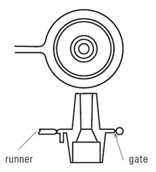
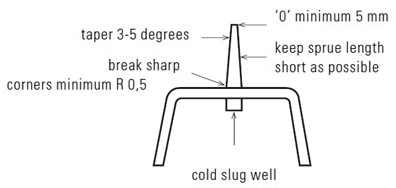
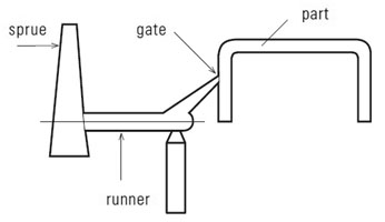
Sprue gates are usually located in the top of the centre of the part with a coldslug-well opposite the gate. They are in general considered to be the best type of gate with respect to filling possibilities. However, they must be machined off as a secondary operation to the injection moulding process.
Design Guide
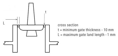
(a) Direct centre sprue
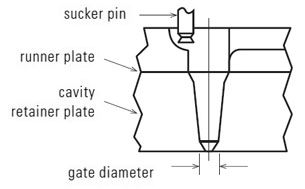
(b) Pin point gate
Similar to a sprue gate, the centre gate has a reverse taper and is self-degating. It is only feasible in a 3-plate tool because it must be ejected separately from the part, in the opposite direction. The gate must also be weak enough so that it will break off without damaging the part.
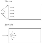
There are basically two gate types: the round gate like tunnels, direct sprues and pinpoints, and the rectangular shaped gate such as tab gates and film gates. In general, point gates create high orientation levels in the gate area, which will frequently lead to distortion, whereas wider film or tab gates tend to bring a more uniform orientation into a component. If a point gate is really essential, sometimes an increase in the number of gating points can bring a more uniform orientation pattern to a component, as well as giving better control in the holding pressure stage due to shorter flow lengths.
As general recommendations, gates should be:
- As large as possible to permit high speed and low shear material flow
- Radiused to reduce shear and facilitate flow
- Designed to include a cold slug well to catch the cooled melt front
- Located strategically to control weld line locations and flow length
- In thicker areas for injection moulded parts
Gating
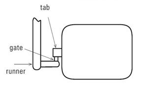
(c) Tab gate
A tab gate is a straight gate into the side of a part. It is very inexpensive to machine. However, it must be removed from the part after moulding which leaves a mark on the edge or side of the part. Due to sharp angles in the gate area, melt shear can be more severe for a tab gate in comparison to the similar but preferred fan gate.
(d) Fan gate
The fan gate is similar to a tab gate but provides large blending radii to reduce shear. A fan gate must be trimmed or machined off and will leave a mark. However, it is the best type of side gate for material flow.
(e) Tunnel or submarine gate
These are very small gates on the sides of a part. They are self-degating and leave very small marks, but cause large amounts of shear in the material. Tunnel gates should have an included
angle of approximately 45 degrees.
(f) Jump gate
The jump gate provides gate location on the bottom of the edge of the part. This is very desirable from an aesthetic point of view, but can be expensive to
machine and cause problems with shear.
(g) Diaphragm gate
A circular gate inside the end of a cylindrical part section, the diaphragm gate is ideal for the filling of circular parts. This is because no weld line forms when the resin enters all of the way around the cylinder. However, this gate is among the most expensive to remove since it requires a mechanical operation.
(h) Ring gate
In this construction, a large diameter runner goes all of the way around the outside end of a cylindrical part and material enter from all sides. As with diaphragm gates, ring gates are very good for circular section parts. They contain the weld line in the gate area and do not typically produce any weld lines in the part. However, they must also be mechanically removed. Ring gates are relatively inexpensive because they can be put in the parting line of the mould and easily machined in the mould half.